Consider a DOT contractor deliverable in Ohio. The flight is clean — 80 percent overlap, RTK-fixed positions on every image, five GCPs surveyed in NAD83 State Plane Ohio South with NAVD88 orthometric heights. Processing looks perfect. Checkpoint RMSE lands under 3 centimeters horizontal, 4 centimeters vertical. The operator exports and sends.
Two days later, the project engineer calls. The orthomosaic is shifted 1.2 meters from the design surface. The elevation model is off by 37 meters.
The flight was fine. The GCPs were fine. The processing was fine. The export landed in WGS84 with ellipsoidal heights instead of NAD83 State Plane with NAVD88. A five-second dropdown menu selection — and the entire deliverable is useless.
Coordinate reference systems are the number one source of deliverable errors in drone mapping. Not overlap. Not GCP placement. Not camera calibration. CRS.

The CRS Stack: What Drone Operators Actually Need to Know
A coordinate reference system defines how locations on Earth get represented as numbers. That is the textbook answer. Here is the practical one: a CRS is a contract between your data and the real world. Get it wrong and your data says one thing while the ground says another.
Every CRS has three components you need to understand:
Datum. The mathematical model of the Earth’s shape that your coordinates reference. WGS84 and NAD83 are datums. They use slightly different ellipsoids, and as of 2026, NAD83(2011) and WGS84(G2139) differ by roughly 1 to 1.5 meters across the continental US. That difference grows at about 2.5 centimeters per year because the North American plate is moving relative to the global reference frame.
Projection. The method for flattening the curved Earth onto a 2D plane. UTM zones, state plane zones, and Web Mercator are projections. Each one distorts something — area, distance, angles — and the job is to pick the one that distorts least for your project area. State plane keeps distortion under 1 part in 10,000 within each zone. UTM keeps it under 1 part in 2,500. For survey work, state plane wins.
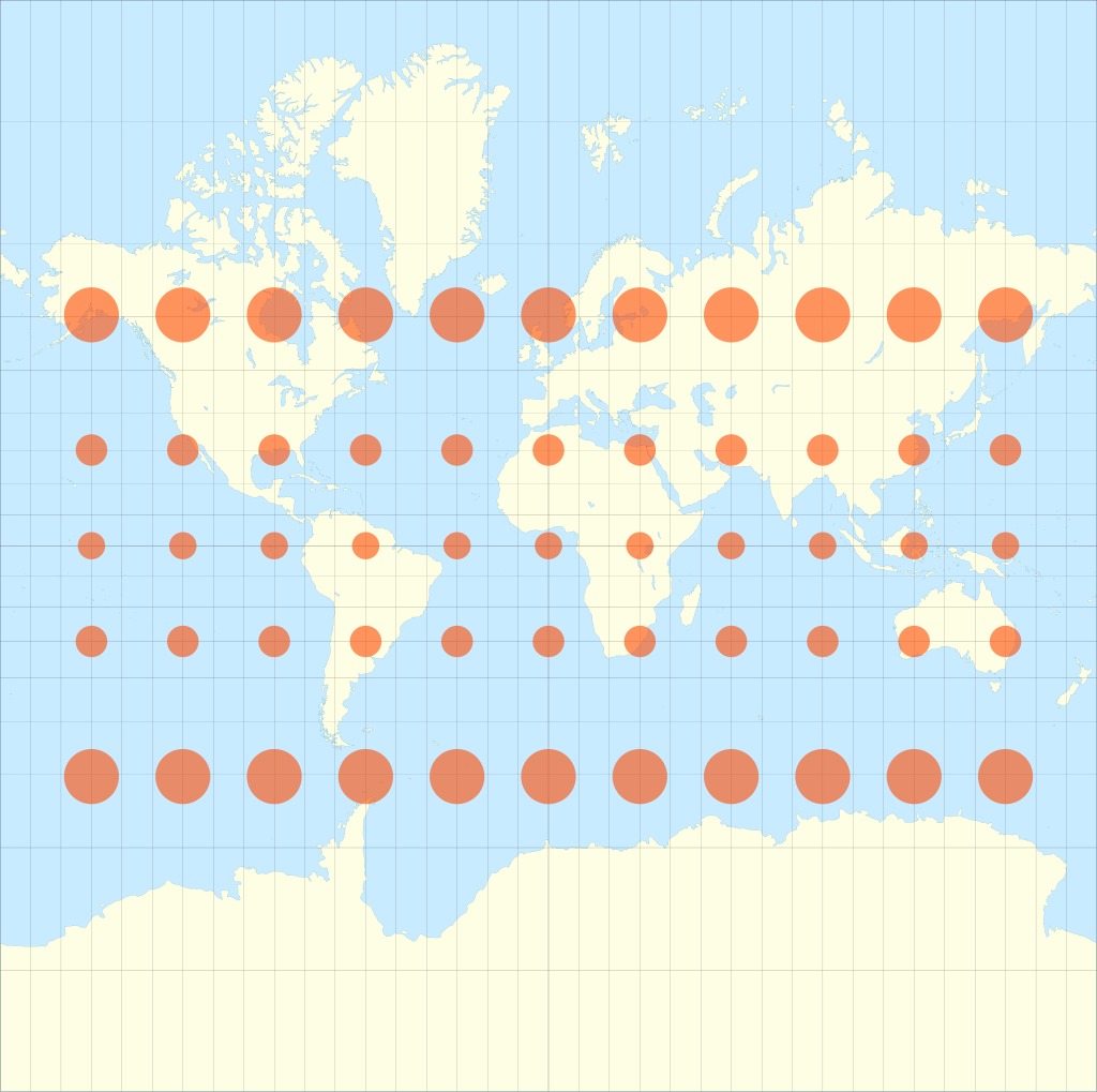 Eric Gaba (Sting), via Wikimedia Commons, CC BY-SA 4.0
Vertical datum. The reference surface for elevations. This is where most drone operators get burned. Your drone records ellipsoidal height — distance above the WGS84 ellipsoid. Your client almost certainly wants orthometric height — distance above mean sea level, referenced to NAVD88. The difference between ellipsoidal and orthometric height ranges from about -8 meters to -53 meters across the continental US. That is not a rounding error. That is a building-sized offset in your elevation data.
WGS84 vs NAD83: The Difference That Software Hides
Most processing software treats WGS84 and NAD83 as interchangeable. They are not.
WGS84 is maintained by the US Department of Defense and periodically updated to align with the International Terrestrial Reference Frame. NAD83 is maintained by the National Geodetic Survey and was last updated in 2011 — NAD83(2011), epoch 2010.0. Since that epoch, the North American plate has moved roughly 2.5 centimeters per year relative to the ITRF. In 2026, that is 40 centimeters of accumulated drift since the 2010 epoch.
To put it plainly: if your RTK base station is broadcasting corrections in NAD83(2011) and your processing software assumes WGS84(G2139), you are starting with over a meter of horizontal offset before you process a single image. Your GCPs — surveyed in NAD83 — will try to correct it, but if you have fewer than five, the bundle adjustment may absorb the datum shift into camera calibration instead of correcting it. The result: locally consistent data that is systematically wrong.

The fix is straightforward but requires discipline. Know which datum your base station uses. Know which datum your GCPs are in. Set your processing software to match. Use EPSG codes — never rely on the name alone. “NAD83” in a dropdown could mean NAD83(1986), NAD83(HARN), NAD83(CORS96), or NAD83(2011). Those are different coordinate systems with different coordinates for the same point on the ground.
Geographic vs Projected: Why Units Matter
Your drone records positions in geographic coordinates — latitude and longitude in decimal degrees. That is fine for navigation. It is terrible for measurement.
Geographic coordinates use angular units on a curved surface. One degree of longitude is 111 kilometers at the equator and zero at the poles. You cannot measure distance, area, or volume directly in geographic coordinates without spherical math that most GIS users — and most processing software defaults — do not apply correctly.
Projected coordinates flatten the Earth onto a 2D grid with linear units — feet or meters. When a DOT engineer opens your orthomosaic in AutoCAD, they expect to measure distances in US survey feet in state plane coordinates. If your GeoTIFF is in WGS84 geographic coordinates, their measurements are wrong. Not slightly wrong. Fundamentally wrong.
State plane zones are the standard for US civil engineering and survey work. There are 124 zones — some states have one, California has six, Alaska has ten. Each zone uses either a Lambert conformal conic projection (for states wider than they are tall) or a transverse Mercator projection (for states taller than they are wide). The zone boundaries follow county lines.
If you are flying a project in Hamilton County, Ohio, your output CRS is NAD83(2011) State Plane Ohio South. EPSG:6550 is the meters definition; EPSG:6551 is US survey feet — pick the one your client specifies. Not Ohio North. Not UTM Zone 16N. Not WGS84. The EPSG code is not optional — it is the only unambiguous identifier for the coordinate system.
UTM zones work for projects that do not have a state plane requirement, especially international work. There are 60 zones worldwide, each 6 degrees of longitude wide. UTM is metric and uses a transverse Mercator projection. Most processing software defaults to UTM because it is simple and globally applicable. That default is fine for internal QA. It is not fine for DOT deliverables.
Vertical Datums: Where Drone Operators Lose the Most Money
Horizontal coordinate errors are visible — your orthomosaic shifts relative to the client’s design surface, and someone calls. Vertical datum errors are invisible until earthwork volumes are wrong, grading plans fail in the field, or a contractor moves 3,000 cubic yards of dirt that did not need to be moved.
Here is the vertical datum stack for drone work in the US:
Ellipsoidal height (h). What your drone GNSS records. Distance above the WGS84 ellipsoid. Not meaningful for engineering — nobody grades a building pad to an ellipsoidal height.
Orthometric height (H). What your client wants. Distance above the geoid — the equipotential gravity surface that approximates mean sea level. In the US, orthometric heights reference NAVD88.
Geoid height (N). The difference between the ellipsoid and the geoid at a given location. The relationship is simple: H = h - N. Across the continental US, N ranges from about -8 meters in the southeast to -53 meters in the Rocky Mountains. The current best model is GEOID18, published by NGS.

If you skip the geoid correction — and I have seen operators do this on every project for years — your elevation model is wrong by the local geoid separation. In Denver, that is about -18 meters. In Miami, about -28 meters. Your elevation surface says a parking lot is at 1,628 meters when it is actually at 1,610 meters. The client does not catch it immediately because the relative shape of the surface looks correct. They catch it when they bring the drone surface into a project that uses NAVD88 benchmarks and nothing lines up.
GEOID18 is accurate to roughly 1-2 centimeters standard deviation when used with NAD83(2011) ellipsoidal heights. That is better than most drone surveys achieve in the vertical axis. Use it.
Software Defaults Are Wrong: Metashape, Pix4D, and ODM
Every major photogrammetry platform has CRS defaults that will produce incorrect deliverables if you accept them blindly.
Agisoft Metashape (v2.1+)
Metashape imports images in WGS84(EPSG:4326) by default. The internal processing coordinate system is WGS84. That is correct for processing — Metashape handles the internal math in a global frame and transforms on export.
The critical settings:
- Reference pane > Coordinate System. Set this to match your GCP datum. If your GCPs are in NAD83(2011) State Plane, set this to the matching EPSG code. Metashape will transform the WGS84 image positions to match.
- Use height above geoid. Check this box. Load the GEOID18 .tif file from NGS. Without this, Metashape uses ellipsoidal heights — your elevation model will be off by the local geoid separation.
- Export CRS. When exporting orthomosaics and DEMs, set the output coordinate system explicitly. Do not assume the export CRS matches the Reference pane CRS. Click the projection dropdown in the Export dialog and verify the EPSG code.
The mistake I see most often: operators set the Reference pane to NAD83 State Plane but leave the vertical datum as “ellipsoidal.” The horizontal coordinates are correct. The elevations are wrong by 20-40 meters. Nobody catches it until the data hits a project with surveyed benchmarks.
Pix4Dmapper / Pix4Dmatic
Pix4D defaults to WGS84(EPSG:4326) horizontal and EGM96(EPSG:5773) vertical — unless the camera is in their database or the images carry correct XMP tags. EGM96 is a global geoid model from 1996. It is not NAVD88. The difference between EGM96 and GEOID18 varies by location but can exceed 1.5 meters in parts of the US.
The critical settings:
- Image Coordinate System. Verify this matches your drone’s actual output. DJI RTK drones tag images in WGS84 with ellipsoidal heights — not EGM96.
- Output Coordinate System. Set this to the client’s required CRS using the EPSG code. Pix4D’s search function accepts EPSG codes directly.
- GCP Coordinate System. This is separate from the image and output systems. If your GCPs are in state plane with NAVD88, set the GCP coordinate system accordingly. Pix4D handles the transformation internally.
Pix4D’s documentation says it clearly: “For clear and unambiguous identification of a CRS, the use of EPSG codes is strongly advised. Relying on CRS names alone can be ambiguous and may lead to misinterpretation.”
OpenDroneMap / WebODM
ODM defaults to WGS84 and automatically selects the appropriate UTM zone based on image location. This works for basic mapping. It does not work for client deliverables in state plane or NAVD88.
ODM processes everything internally in a WGS84-based frame. If you supply GCPs in a different coordinate system, ODM reprojects them to WGS84 for processing. The output GeoTIFFs are in the auto-selected UTM zone.
For custom output CRS, use the --proj flag or reproject the output GeoTIFFs using GDAL after processing:
gdalwarp -s_srs EPSG:32617 -t_srs EPSG:6550 input.tif output.tif
That command transforms from UTM Zone 17N to NAD83(2011) State Plane Ohio South. For vertical datum conversion, use NOAA’s VDatum tool or PROJ’s vertical pipeline — GDAL alone does not handle geoid corrections out of the box without a compound CRS definition.
ODM is the platform where I see the most CRS errors in delivered data. Not because the software is bad — it is excellent for the price — but because the CRS workflow requires manual intervention that Metashape and Pix4D handle through GUI settings.
Client Specs: What They Actually Require
Different agencies and clients specify CRS differently. Here is what you will encounter:
DOT projects. State plane coordinates in the local zone, US survey feet, NAD83(2011), NAVD88 with GEOID18. Every state DOT publishes survey standards. If you are flying for a DOT project and you do not know the state plane zone, stop and ask before you fly. The zone determines everything downstream.
USACE projects. EM 1110-1-1005 governs. USACE typically requires NAD83 state plane or UTM, NAVD88 orthometric heights, and compliance with ASPRS accuracy standards. Accuracy classes are defined against independent checkpoints — not against the GCPs you used for processing. If you report accuracy without independent validation, the deliverable is non-compliant.
Municipal and county work. Varies wildly. Some counties use NAD83(HARN) instead of NAD83(2011). Some use local coordinate systems with custom projections. Always request the project CRS specification in writing before you fly. “Match our existing GIS data” is not a CRS specification — it is an invitation to guess wrong.
ASPRS standards. The Positional Accuracy Standards for Digital Geospatial Data (2023 edition) define accuracy classes by RMSE thresholds. Class I horizontal requires RMSE of 2.5 centimeters or better. These standards assume the data is in a well-defined CRS with proper datum and projection. Claiming ASPRS Class I accuracy on data delivered in the wrong coordinate system is meaningless.
Private engineering firms. Most use state plane. Some use project-specific local coordinate systems with a defined origin point — grid-to-ground factors applied. If the client mentions “ground coordinates” or “project coordinates,” they have a local system. Get the transformation parameters before you export.
The Checklist: CRS Workflow for Every Project
This is the sequence I follow. It has eliminated CRS errors from my deliverables.
Before the flight:
- Get the CRS specification in writing. EPSG code preferred. If the client says “state plane,” confirm the zone and units. If they say “NAD83,” confirm the realization — NAD83(2011) or something older.
- Confirm the vertical datum. NAVD88 with GEOID18 is the US standard. If the client does not specify, use NAVD88. Document that you used it.
- Survey GCPs in the project CRS. Or transform them using NGS tools. Do not rely on processing software to handle GCP datum transformations unless you have verified the transformation parameters it applies.
During processing:
- Set the image coordinate system to match your drone’s output. WGS84 with ellipsoidal heights for most DJI platforms.
- Set the GCP coordinate system to match your survey data. If GCPs are in state plane with NAVD88, use the compound EPSG code or set horizontal and vertical systems separately.
- Apply the geoid model. GEOID18 for NAVD88 work in the US. Download from NGS, load into your processing software.
- Set the output CRS before exporting. Verify the EPSG code. Do not trust the dropdown name.
Before delivery:
- Open the exported GeoTIFF in QGIS or ArcGIS. Check the CRS metadata — Layer Properties > Source > CRS. Verify it matches the client spec.
- Compare a known checkpoint. Take a surveyed point in the client’s coordinate system and check its position in your deliverable. If the horizontal or vertical offset exceeds your accuracy spec, something is wrong with the CRS chain.
- Document the CRS in your delivery metadata. Include the EPSG code, datum realization, vertical datum, geoid model, and epoch in your project report. If the client opens the file in five years with updated software, this documentation prevents confusion.

Real World Examples
The 37-meter elevation offset. The example from the introduction. Exported ellipsoidal heights instead of NAVD88 orthometric. The client’s grading contractor bid earthwork quantities based on that surface. Every elevation was 37 meters too high. Caught before construction, but the re-export costs a day — and the client’s trust takes months to rebuild.
The 1.2-meter horizontal shift. Processed in WGS84, delivered to a client working in NAD83(2011). The orthomosaic landed a meter and a half from the design surface. The client assumed my GCPs were bad. They were not — the datum mismatch was the entire error.
The wrong state plane zone. Operator flew a project on the border of two state plane zones. Processed in Zone South. Client’s project was in Zone North. The distortion at the zone boundary introduced 8 centimeters of systematic error across the site — well within typical drone accuracy, but completely artificial. The data was accurate in the wrong coordinate system.
The EGM96 vertical surprise. Operator used Pix4D defaults — EGM96 for the vertical datum. Client expected NAVD88. The difference at that location was 1.3 meters. The contour map showed a drainage pattern that does not exist. The grading plan was redesigned around a phantom low point.
Every one of these errors was a settings issue. The flights were good. The processing was good. The CRS was wrong.
Bottom Line
Coordinate reference systems are not glamorous. Nobody posts about EPSG codes on social media. But CRS errors are the fastest way to destroy a deliverable that was otherwise perfect — and the fastest way to lose a client’s confidence.
The rules are simple. Get the CRS specification before you fly. Use EPSG codes, not names. Apply the geoid model. Verify the output before you deliver. Document everything.
Your drone captures the data. Your processing software builds the model. The coordinate reference system determines whether that model lives in the same reality as the rest of the project. Get it right.
For more on positioning methods and accuracy validation, see RTK vs PPK: Which Should You Use?.